Finished Product Up Front

Intro
So the guts of this speaker build is basically what I've been using for my mains for the last 6 or 7 years. The tweeter is a Bohlender Graebener Neo3-PDR Planar Tweeter and the woofer is an Aurum Cantus AC-130MKII. I'm still amazed by the AC's ability to be detailed and dig down lower than any 5-1/4" driver has any right to.
Those were in a Mass Loaded Quarter Wavelength Tube (ML-QWLT) and had an F3 of 33Hz which is pretty stellar for a little 5-1/4" driver. I have been meaning to redo the cabinets for about 5 yeras, but never got around to it since even though they were ugly....

they sounded great. Now that I have a few actual woodworking projects under my belt I thought it was a good time to revisit the idea of making them "pretty".
I had never used veneer before and thought it'd be a good idea to work on something smaller than a tower for my first attempt. I had the speakers but not the crossover parts on hand to make a second pair so I thought I'd build a pair of bookshelf sized speakers for the rear channels and then move on to making the towers.
So now that that's out of the way....
Drawings/Modeling/etc.

Modeling the box itself for a vented alignment, ended up around 11.4L (.4ft³) tuned to 46Hz I'll have to do a sweep to see what it is actually tuned to... I didn't get all fancy and figure out things like bracing volume and such. My ear says they started dropping off around 50Hz so it should be fairly close. This was modeled in "Unibox" which is just a free and powerful excel spreadsheet fairly commonly used on the speaker building forums.

Now that I had the appropriate box volume and port sizing I could figure out overall dimensions. The original design for the XO called for a 10" wide baffle, but I did a little bit of modeling and the frequency response wasn't too too effected by going slightly narrower. Window bracing is ~1" wide all around and rounded over. The bracing will make a bit more sense later
Electronics
I designed these a few years back and can't seem to find the response curves or my original crossover files but here are the schematics and general layout of the board. The tweeter is reverse polarity.


It's a fairly simple 3rd order on the tweeter with some padding to bring it's sensitivity down to match the woofer. 3rd order on the woofer too with a baffle step compensation circuit.

The finished boards

And underside of the board, my soldering "skills" aren't great, but hey, it works.
Build
This was a pretty straight forward build, didn't really get any assembly pictures of the main box since it took about 15 minutes to cut everything and assembly was less than an hour or so. I did end up using 16GA brad nails for assembly which was more because I wanted to use my new toy than actually having a reason to do so. I drove them beneath the surface and back filled with wood putty to get it flush. All the material is 3/4" MDF.

This is the brace that sets inside the cabinet in the front, I just eyeballed where the windows should be and used a fostner bit to get radius'd corners.

Cut the rest of the window with a jig saw

For the front baffles I used a combination of walnut, tiger maple, and "rosewood". The rosewood isn't true rosewood, but some species from the Solomon Islands near New Guinea that I got for free. It seems to be in the sapele family? Idunno but it's pretty and I had a piece that was too thin to really use as anything but an accent so here it is.

Laying out the speaker geometry to flush mount the woofer. I tried to mark the start/stop points as well as I could.

First step was to cut the radius'd corners, used a circle jig for this part and carefully stopping at the start of the straights.

Which was kind of a pain since this is the window I was looking through...

After the corners were done I did the flats with an edge guide.
For all these I would go to one side of the cut, plunge to full depth and go back to my start point do a full plunge there and do 3-4 shallow passes along the rest of the cut. Having the full depth already done on the ends of the cut meant that I didn't have to hit my "stop" point perfectly every time, just on the first plunges.

and then the inner section where the speaker would rest on again with the circle jig

along with the through hole. In total I think this actually took longer than the entire cutting/gluing/etc. of the main cabinet

Using the edge guide again I roughed out the hole for the tweeter, since all that was hidden I wasn't too exact and did a lot of it by hand if that wasn't readily apparent.

I wanted a fairly shallow chamfer on the sides so broke out the hand plane

Forgot a few pictures here, but I taped down the baffle to the box with painter's tape and used a drill press to locate the 6 screws that hold the baffle on the front. That way if any of the holes were off it'd be "wrong" on both the baffle and the rest of the box and still work.
This was a test fit of everything you can see some inconsistent gaps around the woofer, might have to try and dial that in for the towers.

on the interior brace I put in some threaded inserts (get these from McMaster-Carr, they are nearly 10x more expensive if you go to Lowes/HD) using my through holes as guides.
You can see here I used a ring around the port since I had to cut the hole after assembly and didn't thing the PVC would adhere very well without it. Normally I'd cut a recess for the PVC to slide into. The brace in the center is also sized (kinda) so that the inside baffle in inset from the main case slightly for weather stripping.
Everything is glued/brad nailed together.
Finishing

After everything was drilled I was ready for veneer, this was my setup and I did one side of each at a time. I picked up some walnut veneer and heat sensitive glue from veneersupplies.com. After cutting a section about ~1/4" larger than the panel I just taped them down to something flat so they don't curl up while they dry which was something I learned on a test piece

Applied a very thin layer of glue on both the box and the veneer using a rubber roller I also got from veneer supplies. I also marked each piece with an orientation arrow so both speakers would match

In about a half hour or so it was dry and ready to be ironed on. I had some cracking issues with my test piece so I wet down the veneer a bit with a spray bottle and that seemed to mitigate the issue for the most part.

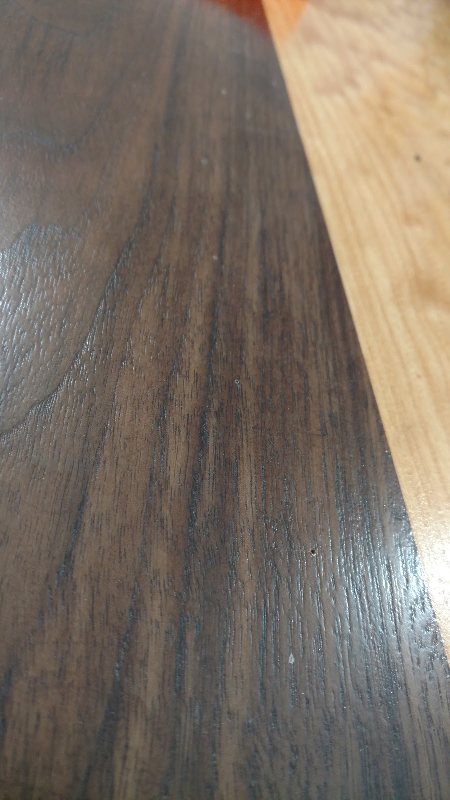
Using a utility knife I cut off the excess fairly closely and then used a plane to flush it up which worked surprisingly well. Another method I also used was to lay a plane blade (without the body) flush with the side and use that to remove it. That seemed to be a bit more sensitive to splitting the wood if you weren't extremely careful with grain direction. Might be less of an issue with a less brittle veneer though. This is my first time working with real veneer so I am mostly just talking out my ass...

So this looks like I'm going backwards... which I was.. because spray paint is the devil. The first attempt ended up looking terrible and had some crackling so I used a filler primer and got things a lot more flat and smooth

and still managed to mess it up. I noticed some dust and even though it had been drying for a few hours the cloth I used to dust them off still managed to scrape the paint...

Moving on... applied my usual few coats of Arm-R-Seal to the veneer (3 coats gloss 1 satin). I also lightly sanded the scratches and fingerprints (that came 6 hours after spraying...) in the paint and just applied some Arm-R-Seal to that as well and it's "good enough" for the back of the speaker that won't ever be seen.

Here is everything wired up and the walls lined with ~1.5" of mineral wool. I put some weather stripping around the face so it seals up when the baffle bolted on.

All that was left was to bolt the faces on and fire them up.


